Prior to commissioning, one should first understand the production process. It is necessary to grasp the design principles, performance parameters, and target specifications of the electrical drive control system. Additionally, one must be familiar with the characteristics of all components and control units within the system, as well as the performance and operating methods of the instruments and equipment used during commissioning. Based on this preparation, a comprehensive commissioning plan should be formulated and implemented accordingly.
Inspection of equipment, wiring, and insulation must be conducted prior to commissioning.
There are no rigidly defined procedures for commissioning soft starter systems. However, the process should generally follow the principle of “no-load first, then light load, and finally heavy load.” The following outlines the commonly adopted methods and sequence for your reference.
General Inspection
(1)Visual Inspection
After the electrical control equipment is installed in position, a general visual inspection shall first be conducted. The visual inspection of all electrical control equipment shall comply with the provisions of Clause 4.2 of the standard GB/T 3797-1989 “Electrical Control Equipment – Part 2: Electronic Control Equipment Incorporating Electronic Components.
Check the following items one by one
Verify that the quantity, model, specifications, and technical parameters of the electrical control equipment and associated equipment (including motors, power conversion units, instrument transformers, transformers, etc.) comply with the relevant code requirements.
Whether the installation quality of all equipment and components complies with the relevant specifications.
Nameplates, symbol plates, and various texts and symbols shall conform to the requirements specified in the drawings and the applicable standards.
Check whether all mechanically operated components (such as cabinet doors, limit switches, interlocks, etc.) operate smoothly and function correctly.
Ensure that the connections of the plug-ins are sound; conduct random spot checks on the contact of plugs (sockets).
Whether the clearance and creepage distances comply with the requirements specified in the technical specifications and standards.
Whether the ingress protection (IP) rating of the enclosure meets the requirements.
The cabinet panel shall be flat and free of undulations. The paint finish shall be clean and aesthetically pleasing, with no defects such as blisters, cracks, or scratches.
All fasteners shall be provided with anti-loosening devices. Fasteners must be tightened until the spring washer is flattened, ensuring there is no looseness.
Safety measures and electric shock protection measures shall be complete and adequate.
The machinery and insulators shall show no signs of deformation, cracking, or damage.
If water-cooled, check that all hose fittings on the water circuits have been tightened
(2)Wiring Inspection
During the wiring inspection, verify the correctness of both internal and external connections of the electrical control equipment against the schematic diagram or wiring diagram.
During the wiring inspection, verify the correctness of both internal and external connections of the electrical control equipment against the schematic diagram or wiring diagram.
During the wiring inspection, pay attention to whether the connections are loose, poorly soldered, or have poor contact.
Connections from the control cabinet to external equipment shall be made via terminal blocks. Generally, no more than three wire lugs shall be connected under a single terminal.
Check whether the types and specifications of all power cables and control cables comply with the design requirements.
Inspect whether the grounding conductors of all equipment and the entire grounding system comply with the design requirements.
Check for misalignment of conductors, cables, and terminals, as well as damage to the cable sheathing.
Check whether the specifications and color codes of the wires comply with the relevant standard requirements.
(3)Insulation Check
Insulation inspection primarily aims to check whether the insulation of electrical equipment has been damaged or eroded by moisture during transportation, storage, and installation. Any electrical equipment found to be damp or damaged should be treated (e.g., dried or repaired) prior to undergoing insulation inspection.
Before measurement, clean all inspected equipment, terminals, and conductors to remove dust, oil, and any items left over from installation.
Prior to measurement, remove dust, oil, and installation debris from all equipment, terminals, and wiring to be inspected.
Insulation resistance is generally measured using a megohmmeter (formerly known as a megger). The voltage rating of the megohmmeter and the standard for insulation resistance shall comply with the provisions specified in Clause 3.8.1 of GB/T 3797-4989, “Electrical Control Equipment – Part 2: Electronic Equipment-containing Control Devices.
For insulation resistance testing, the voltage rating of the insulation resistance tester shall be determined based on the operating voltage (U1) of the circuit.
48V<U1<500V,Set to the 500V range.
500V<U1<1000V,Set to the 1000V range.
1000V<U1<1200V,Set to the 2500V range.
For AC/DC motors, electrical apparatus, and wiring with a voltage rating below 1000V, the insulation resistance shall not be less than 0.5 MΩ. For those rated at 1000V and above, the insulation resistance shall not be less than 1 MΩ or shall be considered based on the formula 1 MΩ per 1000V. For specific control circuits, relay protection systems, and automation control systems, to prevent malfunctions of components and systems, the insulation resistance of each current-carrying circuit to ground shall not be less than 1 MΩ.
When measuring insulation resistance using a megohmmeter, components that cannot withstand the output voltage of the instrument (such as capacitors and various power electronic devices) should be isolated from the circuit or short-circuited. For the individual testing of these components, a megohmmeter or multimeter with a voltage not exceeding their test voltage rating should be used.
Insulation resistance checks generally include the following sections:
Conductive parts to ground (or earth).
Between two separate current-carrying circuits, such as:
Between individual AC phases
Between current and voltage circuits
Between conductive parts and ground
Between control, signaling, and other independent circuits
Between the motor bearings and the base (except for those directly grounded).
Pre-energization Check
(1)General Inspection
Verify that the ambient temperature, humidity, and vibration levels meet the specified standards.
Check for the presence of dust, water droplets, or other foreign matter on the surface.
Check if there are any tools or foreign objects left in the vicinity.
For equipment utilizing water-cooled heat sinks, inspect the water circuit as follows: Connect the inlet and outlet to the water source using a section of insulated hose, ensuring sufficient insulation strength. Circulate water until all piping is completely filled. Check the pressure and flow rate of the main water circuit. Inspect for leaks or blockages. Verify that the water pressure control and protection system operates correctly.
(2)Commissioning of the control circuit
With the main circuit power disconnected, energize the control circuit to perform no-load operation. This is to verify the correctness of all sections and components within the control circuit.
Inspect all circuit breakers and electrical components in both the control and main circuits according to the schematic diagram.
For devices that are inconvenient to test at this stage (such as limit switches and various current relays), artificial simulation methods may be used for verification.
Frequent operation of certain equipment (such as high-voltage switches and high-capacity circuit breakers) should be avoided.
Ensure that all electrical components are correctly wired and operate smoothly, without any jamming, sticking, or sluggishness.
Check for any vibration or noise during the operation of electromagnetic contactors and relays, and ensure that the coil temperature remains normal.
All contacts must make good electrical connection when closed, especially during the operation of protective and interlocking circuits, which should respond promptly.
1. System Interruption Check: Ensure that the system is cut off quickly and reliably.
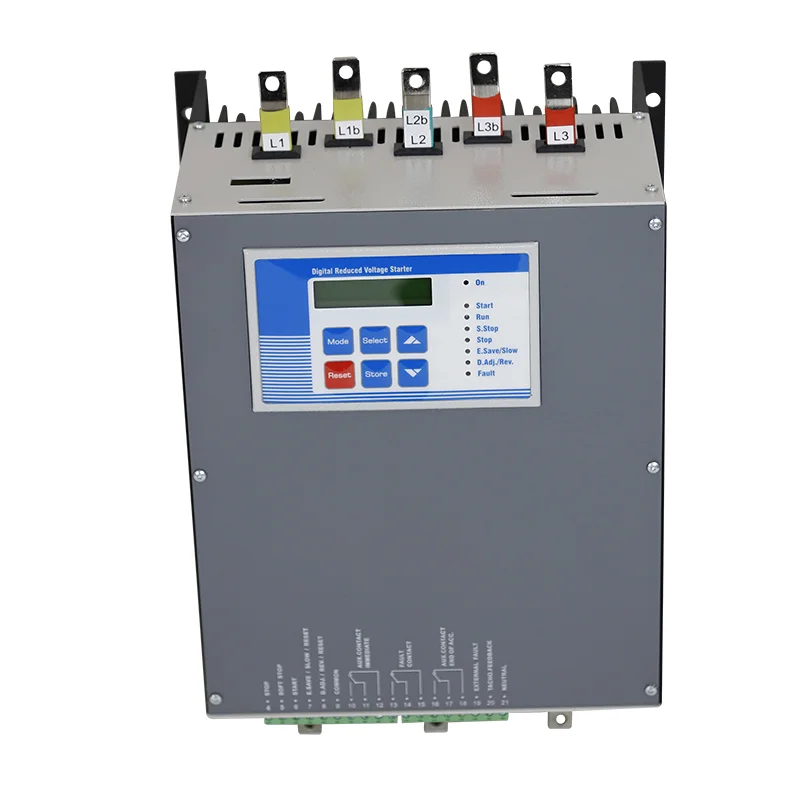
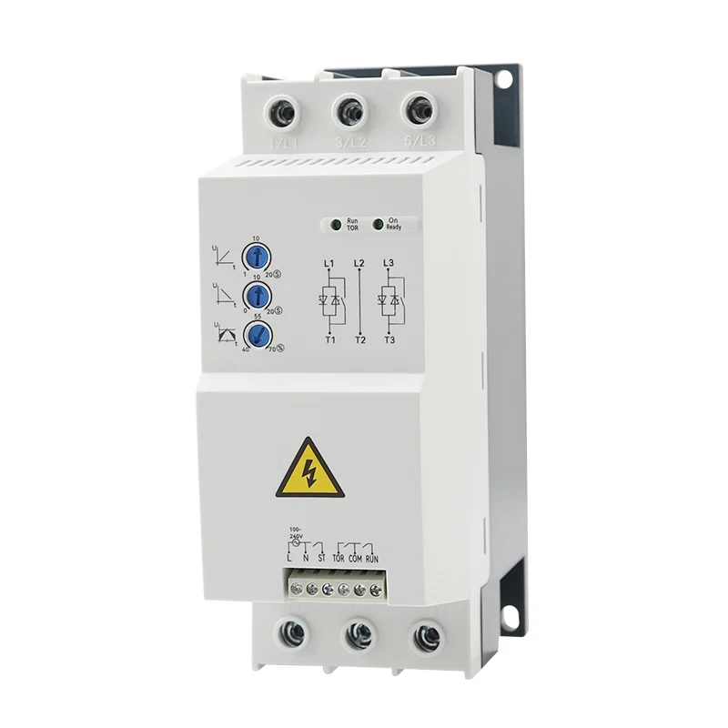
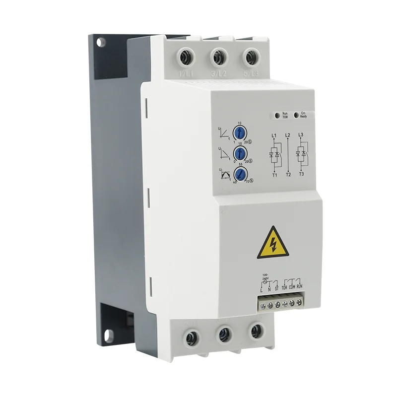
2. Soft Starter Verification: Check that the control system of the soft starter operates normally with external equipment, including all interlocking and protective functions.
Struggling to stay cool in South America? Compare evaporative cooler vs portable air conditioner to find the best solution for your climate and budget. The hot and humid coastline and dry highlands of South America have formed completely unique climate conditions, which have also given rise to diverse cooling needs and various solutions. From evaporative cooler […]
Portable air cooler actually have been gaining more and more attention in the market in recent years. Especially in hot and dry environments, more and more businesses and wholesale buyers are looking for efficient cooling solutions. Portable air coolers are an ideal alternative to traditional air conditioners because of their economical, practical, and environmentally friendly features. […]
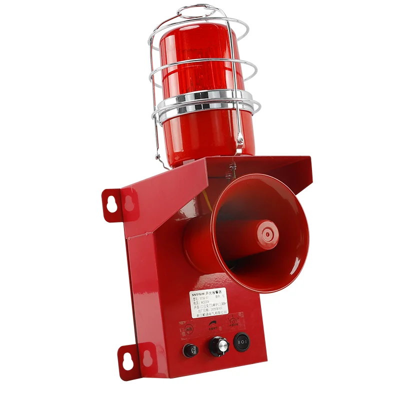
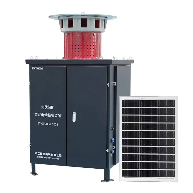
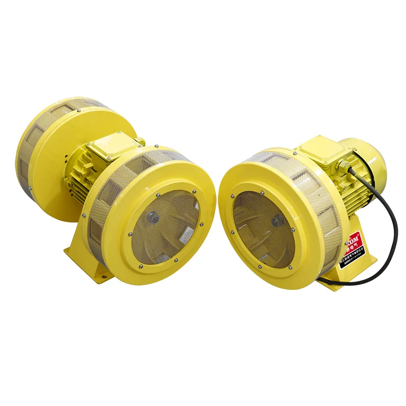
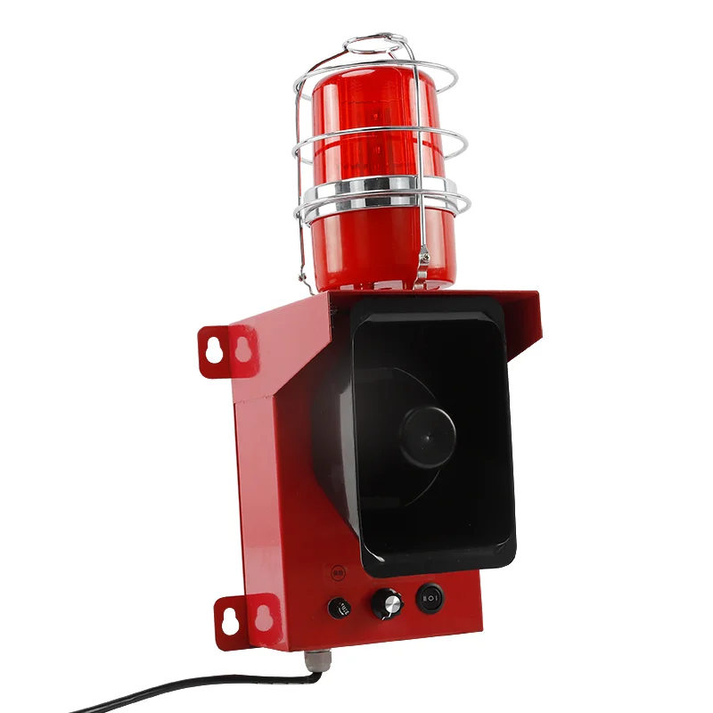
Understanding the differences between Sound and light alarm and motor alarm is crucial for selecting the right system to ensure safety and efficiency. Below we explain the functions and features of these two devices. What is Sound and Light Alarm? A Sound and Light Alarm is a dual-sensory alert system that combines auditory and visual signals to […]
We use cookies to enhance your browsing experience, serve personalised ads or content, and analyse our traffic. By clicking "Accept All", you consent to our use of cookies.