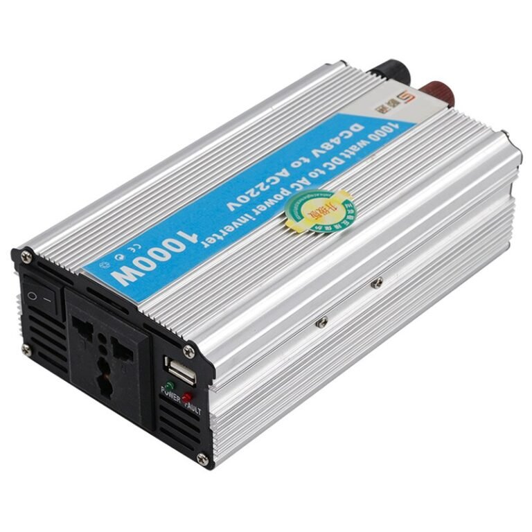
A load-by-load guide to what a 1000 W 48 V to 220 V power inverter actually runs: lighting, fridges, pumps, tools and shop equipment, with the arithmetic behind each verdict.
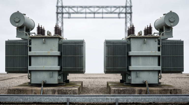
An on-load tap changing transformer corrects voltage while the unit stays live, and the tap position table is where its regulation range is stated. This article walks through a nine-position ±4×2.5% table line by line, explains why currents appear only in the rated row, separates on-load from off-circuit tapping, and lists what to put on the enquiry so the quoted range matches the network.
An intelligent universal circuit breaker is usually ordered from a short specification: a current rating, a voltage, and a breaking capacity. Those three numbers are necessary and not sufficient. This article explains why the frame size is a mechanical platform rather than the current the breaker will run at, what Icu, Ics and Icw each measure and which one governs the design, how the trip unit grade changes what the breaker can protect, and which operating conditions — ambient temperature, altitude, protection degree, installation category and mounting tilt — belong on the enquiry rather than in the maintenance procedure.
Adding a second transformer beside an existing one looks like the cheapest route to more capacity. It often is, but only when four conditions line up exactly: turns ratio and tap position, vector group, impedance voltage and phase sequence. Where they do not, the result is not reduced capacity but circulating current flowing between the units before any load is connected, heat that appears with no explanation, and protective devices that operate without a fault. This article sets out each condition, what happens when one of them is not satisfied, and a five-step check for a proposed pairing that can be carried out before energisation.
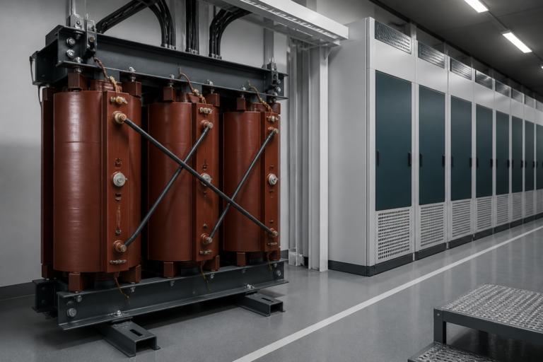
A transformer feeding a plant full of variable frequency drives can run dangerously hot while a clamp meter reads less than its rated current. Harmonic currents are the reason a transformer k-factor exists as a separate specification. This article explains why non-linear loads heat a transformer more than their current suggests - eddy current losses rise roughly with the square of frequency, so the extra heat appears in the windings while the fundamental current stays below the kVA rating - what a K-factor rating does and does not guarantee, why neutral conductors need separate attention under triplen harmonics, and how to size for harmonic currents using measured total harmonic distortion, a load profile, a matched K-factor and a derating factor for the real plant room.
×
Get a Free Quote
We will respond to your inquiry within 24 hours
We value your privacy
To provide you with high-quality consultation and services, we use cookies to store necessary information.