The technical documentation, files, and construction drawings regarding the variable frequency drive (VFD) system have been received. The peripheral electrical installation of the inverter has been completed and accepted as qualified. The installation quality meets the design specifications, the manufacturer’s technical documents, and construction acceptance standards. All related tests conducted during the installation process have been completed and accepted as compliant with the relevant standards.
Furthermore, the personnel are fully familiar with the commissioning technologies, including:
The inverter’s key technical parameters: Voltage, current, power, frequency range, motor speed, acceleration time, and deceleration time.
Operation and programming: Proficiency in the inverter operation manual, parameter programming and setting procedures, and the content and values of main protective functions.
System control logic: A thorough understanding of the overall system control principles, protection mechanisms, and process interlock principles.
2:Preparation and Power-On
After verifying through repeated checks that the inverter is fault-free, close and secure the inverter cabinet door to prevent injury to personnel and equipment accidents upon power-on.
Before energizing, thoroughly read the product manual. If possible, disconnect the motor from the load prior to power-up.
After power-on:
Observe the display: Check the monitor and change the display content according to the manual to confirm normal operation.
Listen for cooling fans: Listen to determine if the cooling fans are rotating.
Once it is confirmed that the inverter is operating normally, proceed to modify and set the function parameters.
3:Inverter Parameter Configuration and Commissioning
When shipped from the factory, inverters come with pre-set default values for their functional parameters. However, these factory settings may not meet the requirements of specific applications. Therefore, certain parameters must be reconfigured according to the actual requirements.
It is important to note that although an inverter may have hundreds of functional parameters, only a small portion of them need to be modified based on specific needs. The majority of the parameters, which are unrelated to the specific application, should remain at their factory default settings.
Unnecessarily modifying or randomly changing parameters without proper judgment can lead to malfunctions or unnecessary complications.
All functional parameters listed in the inverter instruction manual can be modified and reconfigured. However, in typical engineering applications, the parameters frequently adjusted are as follows: operation method, frequency, maximum frequency, rated voltage, acceleration/deceleration time, electronic thermal overload relay, torque limit, and motor pole number.
Setting of Acceleration and Deceleration Time During the operation of production machinery, the acceleration process (or starting process) is a transition from one running state to another, during which production activities are generally not carried out. Therefore, from the perspective of improving labor productivity, the acceleration time should be as short as possible. However, an excessively short acceleration time may easily cause tripping due to overcurrent.
Thus, the basic principle for presetting the acceleration time is to make it as short as possible on the premise that no overcurrent occurs. Usually, you can first preset a relatively long acceleration time and observe the current of the drive system during startup. If the starting current is small, the acceleration time can be gradually shortened until the starting current approaches the upper limit value.
The factors affecting the acceleration time include the inertia of the load and whether the load capacity matches that of the frequency converter. Some loads have no requirements for starting and braking time, such as fans and water pumps, for which the acceleration and deceleration time can be appropriately preset to a longer duration.
Just like the acceleration process, during the operation of production machinery, the deceleration process (or shutdown process) is also a non-productive transition from one state to another. From the perspective of improving productivity, the deceleration time should also be as short as possible. However, as mentioned above, an excessively short deceleration time may easily lead to overvoltage.
Therefore, the basic principle for presetting the deceleration time is to make it as short as possible on the premise that no overvoltage occurs. Usually, you can first preset a relatively long deceleration time and observe the DC voltage of the drive system during the shutdown process. If the DC voltage is low, the deceleration time can be gradually shortened until the DC voltage approaches the upper limit value.
Torque Boost Also referred to as torque compensation, it is used to compensate for the torque reduction at low speeds caused by the resistance of the motor stator winding. Compensation increases the motor torque within the low-frequency range. This parameter can be set to automatic compensation or manual compensation.
When set to automatic compensation, the voltage during acceleration will be automatically boosted to compensate for the starting torque, ensuring smooth motor acceleration. When manual compensation is adopted, an optimal curve can be selected through tests based on load characteristics, especially the starting characteristics of the load. Torque boost and acceleration time need to be considered simultaneously on occasion.
Electronic Thermal Overload Protection .This function is designed to protect the motor against overheating. The CPU inside the frequency converter calculates the motor’s temperature rise based on the operating current and frequency, thereby providing overheating protection. This function is only applicable to the one-inverter-one-motor scenario. In the case of one-inverter-multiple-motors, thermal relays must be installed on each motor respectively. Setting formula for electronic thermal protection (%):= [Rated motor current (A) / Rated inverter output current (A)] × 100%
Overcurrent Protection. Overcurrent protection is designed to protect the frequency converter itself. When the output current of the frequency converter exceeds its rated current, the converter is deemed to be in an
overcurrent state and will send out a protection signal. Overcurrent protection is a critical component for ensuring the safe operation of the frequency converter, because the switching devices of the converter have poor
overcurrent tolerance—if no prompt response is made when an overcurrent occurs, the switching modules may well be damaged. Each type of frequency converter has a preset range for overcurrent protection; generally, the adjustable time range for overcurrent protection is 0–60 seconds, and the overcurrent threshold can be set within 200% of the rated current. The specific settings should be selected according to actual requirements. The causes of overcurrent protection activation in a frequency converter include impact loads, motor stalling, insulation damage and short circuit of the cable between the frequency converter and the motor, insulation damage and short circuit of the motor stator winding, as well as short circuit of relevant connectors at the converter’s output terminal caused by conductive substances.
Limit Frequency. In some operating scenarios, for safety reasons, it is necessary to set an upper limit frequency (fmax) and a lower limit frequency (fmin) to prevent accidents caused by an unintended increase in motor speed due to misoperation of the frequency converter.
Instantaneous Power Failure Restart. To ensure safe operation, all frequency converters are equipped with an instantaneous power failure restart function. This function offers multiple options, such as no restart after instantaneous power failure, restart at the original frequency after instantaneous power failure, and restart from zero frequency after instantaneous power failure. The settings should be flexibly adjusted according to the specific requirements of the application site. For example, a company newly installed a 30 kVA VFD-P series frequency converter to drive its key equipment. When the large motors in the factory started up, the frequency converter tripped and shut down, resulting in significant economic losses. Subsequent inspection of the converter’s function parameters showed that the parameter “d” in 08-04 Instantaneous Power Failure Restart was set to “dO0″—the factory default value, which means no restart after instantaneous power failure. After the parameter was modified to “dO1” (continuous operation after instantaneous power failure), the frequency converter no longer tripped.
Torque Vector Control. Torque vector control is a technology that leverages the similarity between the torque generation mechanism of an asynchronous motor (after vector transformation) and that of a DC motor. The vector control method decomposes the stator current into magnetizing current and torque current, controls them separately, and then outputs the synthesized stator current to the motor. In principle, this enables the motor to achieve the same control performance as a DC motor. With the torque vector control function enabled, the motor can output maximum torque under all operating conditions, especially in the low-speed operation range.
Since the frequency converter can perform slip compensation according to the magnitude and phase of the load current, the motor is endowed with rigid mechanical characteristics—which meet the requirements of most applications without the need to install an external speed feedback circuit for the frequency converter. To activate the torque vector control function, simply set the corresponding function parameter to “Valid”.
There is much more to explain regarding inverters, such as inverter fault displays and troubleshooting, inverter commissioning, and measuring in-circuit resistance of inverters.
Struggling to stay cool in South America? Compare evaporative cooler vs portable air conditioner to find the best solution for your climate and budget. The hot and humid coastline and dry highlands of South America have formed completely unique climate conditions, which have also given rise to diverse cooling needs and various solutions. From evaporative cooler […]
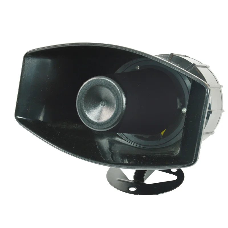
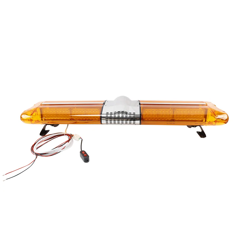
Understanding the differences between Sound and light alarm and motor alarm is crucial for selecting the right system to ensure safety and efficiency. Below we explain the functions and features of these two devices. What is Sound and Light Alarm? A Sound and Light Alarm is a dual-sensory alert system that combines auditory and visual signals to […]
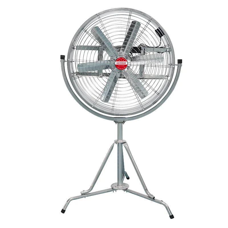
Introduction to Fan in Industrial and Everyday Applications Fan are the unsung heroes of modern life, working tirelessly to keep us cool, ventilate spaces, and ensure machinery operates efficiently. From the air conditioner humming in your living room to the powerful exhaust system in a factory, fans play a critical role. But not all fans […]
We use cookies to enhance your browsing experience, serve personalised ads or content, and analyse our traffic. By clicking "Accept All", you consent to our use of cookies.