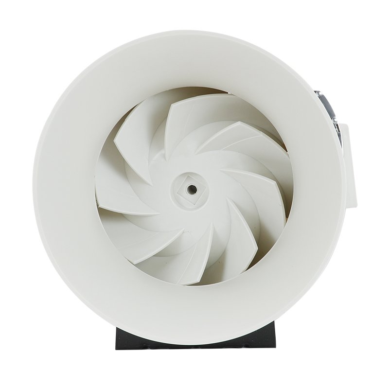
Calculating the capacity of a centrifugal fan is essential for ensuring proper sizing and selection in ventilation, air conditioning, and industrial process systems. Centrifugal fans generate airflow by using rotating impellers to increase the air velocity and pressure. By accurately determining the required fan capacity, engineers and system designers can optimize air movement, energy efficiency, and overall system performance.
To calculate centrifugal fan capacity, several key parameters must be considered, including the fan’s dimensions, operating speed, air density, and system resistance. This article will provide a step-by-step guide on how to calculate the capacity of a centrifugal fan using fundamental principles of fluid mechanics and fan laws.
Step to Step to Calculate Centrifugal Fan Capacity
Step 1: Determine the Fan’s Dimensions
The first step in calculating centrifugal fan capacity is to obtain the fan’s key dimensions, which include:
- Impeller diameter (D): Measure the outer diameter of the fan’s impeller in meters (m).
- Impeller width (W): Measure the width of the impeller from the front plate to the back plate in meters (m).
- Inlet and outlet areas: Determine the cross-sectional areas of the fan’s inlet (A1) and outlet (A2) in square meters (m²).
Step 2: Determine the Fan’s Operating Speed
The fan’s operating speed, measured in revolutions per minute (RPM), directly impacts its capacity. Obtain the fan’s rated speed from the manufacturer’s specifications or measure it using a tachometer. Convert the speed from RPM to radians per second (rad/s) using the following formula:
ω = (2π × RPM) / 60
where:
- ω is the angular velocity in radians per second (rad/s)
- π is the mathematical constant pi (approximately 3.14159)
- RPM is the fan’s operating speed in revolutions per minute
Step 3: Calculate the Fan’s Tip Speed
The tip speed (U) of the impeller is the linear velocity at the outer edge of the impeller. It is calculated using the impeller diameter (D) and the angular velocity (ω) determined in the previous steps:
U = (ω × D) / 2
where:
- U is the tip speed in meters per second (m/s)
- ω is the angular velocity in radians per second (rad/s)
- D is the impeller diameter in meters (m)
Step 4: Determine the Air Density
The density of the air being moved by the fan affects its capacity. Obtain the air density (ρ) based on the operating conditions, such as temperature and pressure. For standard atmospheric conditions (20°C and 101.325 kPa), the air density is approximately 1.204 kg/m³.
If the fan operates under different conditions, use the ideal gas law to calculate the air density:
ρ = (P × M) / (R × T)
where:
- ρ is the air density in kilograms per cubic meter (kg/m³)
- P is the absolute pressure in pascals (Pa)
- M is the molar mass of air (0.02897 kg/mol)
- R is the universal gas constant (8.314 J/mol·K)
- T is the absolute temperature in kelvins (K)
Step 5: Calculate the Volumetric Flow Rate
The volumetric flow rate (Q) is the volume of air moved by the fan per unit time. It is calculated using the continuity equation, which relates the flow rate to the cross-sectional area (A) and the average velocity (v) of the air:
Q = A × v
To determine the volumetric flow rate, use the fan’s outlet area (A2) and the outlet velocity (v2). The outlet velocity can be estimated using the fan’s geometry and the tip speed (U) calculated in Step 3:
v2 = φ × U
where:
- φ is the flow coefficient, which depends on the fan’s geometry and typically ranges from 0.15 to 0.25 for centrifugal fans
Substitute the outlet velocity into the continuity equation to obtain the volumetric flow rate:
Q = A2 × (φ × U)
where:
- Q is the volumetric flow rate in cubic meters per second (m³/s)
- A2 is the outlet area in square meters (m²)
- φ is the flow coefficient (dimensionless)
- U is the tip speed in meters per second (m/s)
Step 6: Consider System Resistance
The actual capacity of a centrifugal fan is influenced by the resistance of the system it is operating in. System resistance is caused by factors such as ductwork, filters, dampers, and other components that restrict airflow.
To account for system resistance, you need to determine the fan’s total pressure (TP), which is the sum of the static pressure (SP) and the velocity pressure (VP):
TP = SP + VP
The static pressure is the pressure required to overcome the system resistance, while the velocity pressure is the pressure associated with the air’s velocity. The velocity pressure can be calculated using the air density (ρ) and the outlet velocity (v2):
VP = (ρ × v2²) / 2
To determine the static pressure, consult the fan’s performance curve or use the fan laws to estimate the pressure drop across the system components.
Step 7: Calculate the Fan’s Power Consumption
The power consumed by the centrifugal fan depends on its capacity, total pressure, and efficiency. To calculate the fan’s power consumption (P), use the following equation:
P = (Q × TP) / (η × 1000)
where:
- P is the power consumption in kilowatts (kW)
- Q is the volumetric flow rate in cubic meters per second (m³/s)
- TP is the total pressure in pascals (Pa)
- η is the fan’s efficiency (typically ranges from 0.6 to 0.8)
The fan’s efficiency is the ratio of the useful power output to the total power input. It accounts for losses due to factors such as mechanical inefficiencies, air leakage, and aerodynamic losses.
Step 8: Optimize and Iterate
After calculating the centrifugal fan’s capacity and power consumption, compare the results with the system requirements and constraints. If the fan’s capacity is insufficient or exceeds the requirements, iterate the process by adjusting the fan’s dimensions, operating speed, or system components.
Optimize the fan selection by considering factors such as energy efficiency, noise levels, and cost. Use the fan laws to estimate the performance of different fan sizes or speeds, and consult manufacturer data to select the most appropriate fan for the application.
By following these steps and iterating as necessary, you can accurately calculate the capacity of a centrifugal fan and ensure optimal performance in your ventilation, air conditioning, or industrial process system.

