The fault display function of a frequency converter is triggered when an internal or external abnormality occurs during its operation. The converter will then shut down for protection and display the cause of the fault on its screen simultaneously. This function provides valuable assistance during the commissioning of the frequency converter. During commissioning, improper parameter settings and unreasonable selection or installation of peripheral equipment may lead to converter tripping and fault display. By utilizing the fault display, operators can adjust the set parameters, modify the irrational configuration of peripheral devices, and thus complete the installation and commissioning of the frequency converter
Fault codes for the same fault may vary with different frequency converter manufacturers
Overcurrent Protection of Frequency Converters
Overcurrent in frequency converters is a common issue encountered during their commissioning. Overcurrent can be divided into two categories: one is start-up overcurrent, and the other is operating overcurrent.
1. Start-up Overcurrent.Start-up overcurrent presents the following phenomena: a. The acceleration time is set too short, and the load has a large inertia. As a result, the motor rotor cannot keep up with the frequency variation of the frequency converter, leading to start-up overcurrent. This issue can be resolved simply by extending the acceleration time setting of the frequency converter.
b. The initial load torque is excessively high, and the output torque of the frequency converter is insufficient to overcome the load resistance torque, thus causing overcurrent. Examples include start-up overcurrent in rotary kilns due to eccentric material stacking angles, and start-up overcurrent in plastic extruders. For this type of overcurrent, it is generally necessary to modify the torque compensation curve of the frequency converter. Attention should be paid to adjusting the low-frequency compensation curve instead of altering the U/f curve of the frequency converter. Alternatively, the torque compensation function of the frequency converter can be set to automatic mode to enable a smooth start via automatic torque compensation. If start-up overcurrent persists, it is advisable to consider increasing the capacity of the frequency converter.
2. Operating Overcurrent Operating overcurrent occurs during the operation of the frequency converter as a result of load fluctuations. This situation mostly arises in systems with shock loads or manually controlled feeding processes. For instance, during the operation of a rotary kiln, high internal temperatures can cause sagging deformation of the kiln shell, leading to a surge in impact current and subsequent tripping. Another example is a waste paper pulper with manual feeding control; an excessive feed rate at any given moment can trigger overcurrent tripping. The aforementioned two scenarios stem from distinct underlying causes of overcurrent and thus require targeted solutions.Match the frequency converter accordingly;
a. if the overcurrent amplitude exceeds the overload capacity of the motor (which is typically 1.8–2.2 times the rated torque of the motor), it is also necessary to increase the motor capacity.
b. If the overcurrent is caused by human factors, do not easily increase the capacity of the frequency converter. Increasing the converter capacity may prevent tripping, but it could result in motor burnout due to long-term continuous overload. The solution is to control the feeding rate.
Overvoltage Protection of Frequency Converters
When the power supply voltage is normal, overvoltage tripping of a frequency converter is generally caused by regenerative energy feedback from the motor. Regenerative energy feedback can be divided into two scenarios: feedback during constant speed operation and feedback during deceleration. Both scenarios share the same mechanism: the motor speed exceeds the output frequency of the frequency converter.
1. Overvoltage During Converter Deceleration Two situations may arise when a frequency converter decelerates:
One is when the load has low inertia and high resistance, such as pump-type loads. During deceleration, the motor speed is always lower than the converter’s output frequency. The motor continuously consumes electrical energy and stops quickly. This type of load will not cause regenerative energy feedback, and the converter will not trigger an overvoltage fault.
The other is when the load has high inertia. As the converter frequency decreases, the motor speed becomes higher than the converter’s output frequency, causing the motor to act as a generator and feed regenerative energy back to the converter. In this case, a braking resistor must be installed on the converter to dissipate the regenerative energy from the motor and bring the motor to a rapid stop. If the resistance value of the braking resistor is too large, the braking current will be too small to fully dissipate the regenerative energy, leading to deceleration overvoltage. In such cases, the resistor must be reselected.
2. Overvoltage During Converter Constant Speed Operation Overvoltage during constant speed operation generally occurs when the load is eccentric. This problem mostly affects periodic energy-storage loads and rotating cylindrical or disc-type loads. When the eccentric load rotates, if the direction of gravity of the eccentric side aligns with the direction of rotation, the load accelerates, causing the motor to feed back regenerative energy and trigger overvoltage. For periodic energy-storage loads like nodding beam pumping units, the motor feeds back energy to the converter once per cycle; this energy is either dissipated through a braking resistor or fed back to the power grid via a regenerative braking network. Overvoltage caused by eccentric cylindrical or disc-type loads usually lasts a short time with a small amount of regenerative energy. Solutions include: first, installing a braking resistor; second, identifying and resolving mechanical issues to eliminate eccentricity.
Frequency Converter Overload
A motor operates under rated current and rated voltage. The product of rated current and rated voltage is defined as rated power. An overload occurs when the converter output exceeds the rated power. Generally, overload means the current exceeds the rated value—but not to an extent that would trigger overcurrent protection. Overload is a time-cumulative process; an overload fault is reported only when the cumulative value reaches the threshold. As shown in Figure 5-1, the converter trips on overload when the overcurrent persists for a certain duration t. The main causes of overload include:
1. Excessive mechanical load. Its main characteristic is motor overheating, which can be detected by reading the operating current on the frequency converter display.
2. Three-phase voltage imbalance. It causes an excessive operating current in a specific phase, leading to an overload trip. Its characteristic is uneven motor heating, which may not be detected by reading the operating current on the display (since many frequency converters only show only the current of one phase on the display screen).
3. Malfunction A fault occurs in the internal current detection circuit of the frequency converter, resulting in an excessively high detected current signal that triggers an overload trip. First, check if the motor is overheating. If the motor temperature rise is low, the priority is to verify whether the preset parameters of the converter’s electronic thermal protection function are reasonable; if the converter still has margin, increase the preset value of the electronic thermal protection function. If the motor temperature rise is excessively high and the overload is a normal condition, it indicates an excessive motor load. In this case, consider whether the transmission ratio can be appropriately increased to reduce the load on the motor shaft. If feasible, increase the transmission ratio; if the transmission ratio cannot be adjusted further, upgrade the motor to a larger capacity.
Check whether the three-phase voltage on the motor side is balanced. If the three-phase voltage on the motor side is unbalanced, further check the three-phase voltage at the converter’s output terminal. If the output voltage is also unbalanced, the fault lies inside the frequency converter. If the converter’s output voltage is balanced, the problem exists in the circuit between the converter and the motor. Inspect that all terminal screws are properly tightened. If there are contactors or other electrical devices installed between the frequency converter and the motor, additionally check that the terminal screws of these devices are tightened and that the contact condition of the contacts is good.
For example, a water supply unit used an Emerson TD2000-4T0300P (30kW) frequency converter to drive a water pump load. During operation, the converter frequently reported the E013 fault (overload). Reviewing the fault current record showed a current of 58A, while the converter’s rated current was 60A. According to the product manual, this pump-specific frequency converter had an overload capacity of 110% of the rated current for 1 minute. During operation, the converter’s output current was equal to or slightly lower than its rated current but did not reach the converter’s cold current threshold. After a period of operation, the overload protection was activated. The converter’s overload protection operates based on an inverse time-limit curve, which varies between models.
This model is a Type P converter, and its inverse time-limit curve is shown in Figure 5-2. When the converter’s output current reaches 95% of the rated current and persists for a duration of t, the ED013 fault is triggered. The converter models are classified into Type G and Type P.
Measurement of the Inverter’s On-board Resistance
(1) Measurement of Input End In-Circuit Resistance
When internal phase loss or similar faults occur in an inverter, they can be diagnosed by measuring the DC resistance. Specifically, measuring the DC resistance at the input terminals involves checking the resistance from terminals R, S, and T to point P or point N.
The Structure of the Ohmmeter Function in an Analog Multimeter Figure 5-8(a) shows the internal wiring diagram of the ohmmeter function in an analog multimeter. As the meter contains an internal power source, when a resistor is connected to the test leads, current flows through the circuit, causing the pointer to deflect. According to Ohm’s law, when the voltage (E) is constant, the current in the circuit (and thus the deflection angle of the pointer) is inversely proportional to the resistance value. Therefore, the resistance value of the component under test can be read directly from the pointer’s deflection angle.
The Conductive Characteristics of Diodes and IGBTs A diode consists of a single semiconductor PN junction and exhibits unidirectional conductivity. When a forward voltage is applied, the diode conducts; conversely, when a reverse voltage is applied, the diode turns off (or blocks).
IGBT as a Field-Controlled Device. An IGBT is a field-controlled device. It can be turned on by applying a certain gate-emitter voltage ( UGEUGE ) between its Gate (G) and Emitter (E), along with a collector-emitter voltage ( UCEUCE ) between the Collector (C) and Emitter (E). Its equivalent circuit is shown in Figure 5-8(c). As can be seen from the equivalent circuit, when measuring a good (intact) device using the ohmmeter function of a multimeter, there should be no conduction between any of the three electrodes. Figure 5-8(d) illustrates the rectifier circuit of the inverter.
Measurement Method .Set a Model 47 analog multimeter to the resistance range “R×10” or “R×100”. (Note: Use a low resistance range; do not use “R×1k” or “R×10k”.) Before taking measurements, perform a zero adjustment (ohms adjustment) on the multimeter.
Connect the black test lead to terminals R, S, and T of the circuit respectively, and connect the red test lead to terminal P. A forward voltage is applied to diodes VD₁ to VD₆. According to the principle of diode conduction under forward voltage, the multimeter pointer will deflect in the positive direction. If the pointer does not move when measuring a specific diode, that particular diode is open-circuited.
Connect the red test lead to terminals R, S, and T of the circuit respectively, and connect the black test lead to terminal P. A reverse voltage is applied to diodes VD₁ to VD₃. According to the principle of diode operation, the diode should block (cut off) under reverse voltage; hence, the multimeter pointer should not deflect. If the pointer deflects when measuring a specific diode, that particular diode is short-circuited.
Connect the black test lead to terminals R, S, and T respectively, and connect the red test lead to terminal N. A reverse voltage is applied to diodes VD₄ to VD₆; therefore, the multimeter pointer should not deflect. If the pointer deflects when measuring a specific diode, that particular diode is short-circuited.
Connect the red test lead to terminals R, S, and T respectively, and connect the black test lead to terminal N. A forward voltage is applied to diodes VD₄ to VD₆. According to the principle of diode conduction under forward voltage, the multimeter pointer will deflect in the positive direction. If the pointer does not move when measuring a specific diode, that particular diode is open-circuited.
(2) Measurement of DC Bus Resistance
Measure the DC resistance on the DC bus to evaluate the quality of the braking unit (braking chopper/resistor). Set the multimeter to the resistance range and measure the resistance between points P and N (connect the black test lead to P and the red test lead to N). If the resistance value is very low, the braking unit may be short-circuited.
(3) Measurement of Output End DC Resistance
The measurement method is the same as that for the input resistance. From the perspective of circuit structure, the six flyback diodes (VD7~VD12) in the inverter circuit are connected in the same configuration as the six diodes in the rectifier circuit. Under normal circumstances, the six switching IGBTs do not conduct between their electrodes. Assuming the six IGBTs are intact (i.e., not short-circuited due to breakdown), they can be considered as open circuits. Therefore, the measurement method for the six flyback diodes is identical to that for the six rectifier diodes.
It should be noted that short-circuit faults in the main circuit—whether in the rectifier or switching devices—will cause severe overcurrent, preventing the inverter from starting.
Conversely, if a device develops an open-circuit fault:
A single open-circuit rectifier diode will cause input phase loss and欠电压 (Undervoltage).
A single open-circuit output IGBT will cause output phase loss.
When a device is open-circuited, replacing it with a component of the same specification will generally restore normal circuit operation. However, if a device is short-circuited, simply replacing the faulty component is insufficient. A thorough inspection of related components is required because a short-circuit fault often has a wide ripple effect, meaning many other components are likely to have been burned out simultaneously.
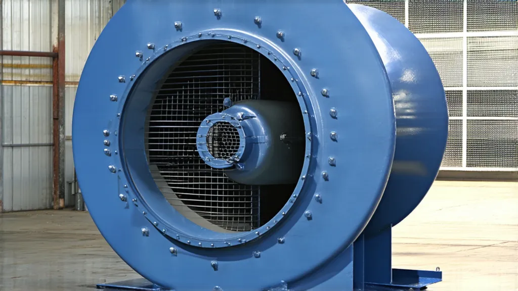
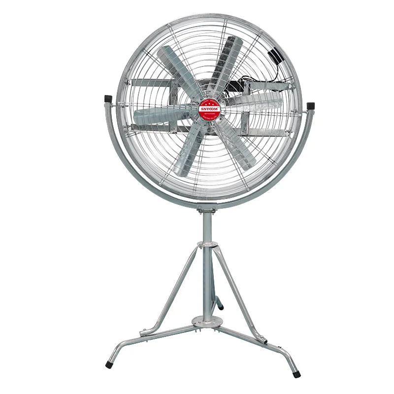
In industrial settings, proper ventilation and air movement are crucial for maintaining a safe and productive work environment. However, many facilities struggle with stagnant air, heat buildup, and poor air quality. Without effective air circulation, these issues can lead to uncomfortable working conditions, reduced equipment efficiency, and even potential health hazards for employees. Ignoring these […]
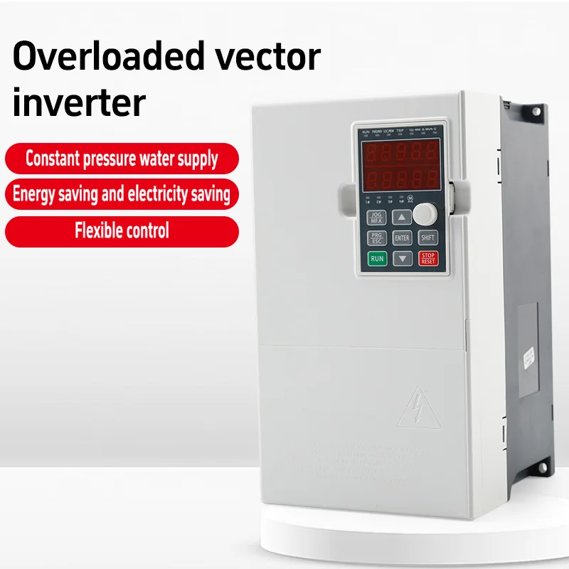
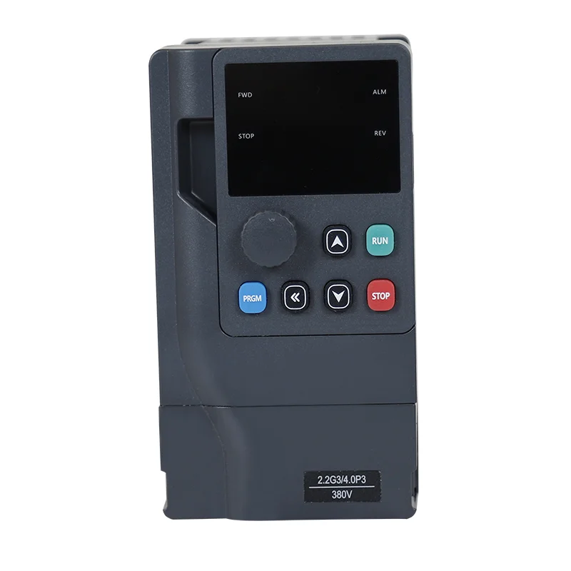
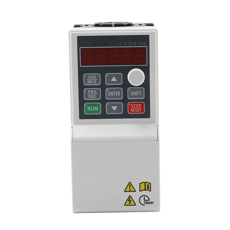
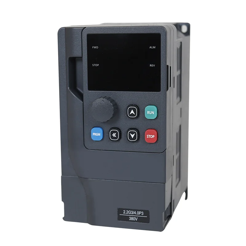
What is a frequency converter? Frequency converter is a kind of power control equipment which uses power electronics technology to change the power supply frequency and voltage of motor and realize motor speed control. It is widely used in energy saving and speed control systems of industrial loads such as fans, pumps and compressors. The […]
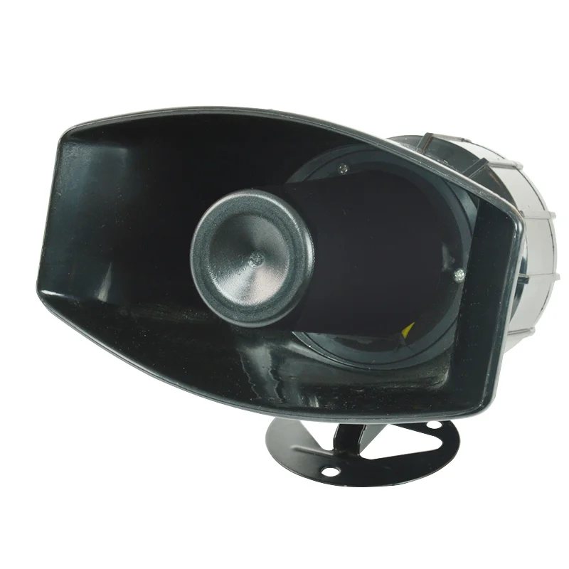
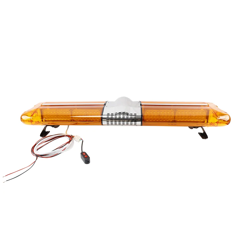
Understanding the differences between Sound and light alarm and motor alarm is crucial for selecting the right system to ensure safety and efficiency. Below we explain the functions and features of these two devices. What is Sound and Light Alarm? A Sound and Light Alarm is a dual-sensory alert system that combines auditory and visual signals to […]
We use cookies to enhance your browsing experience, serve personalised ads or content, and analyse our traffic. By clicking "Accept All", you consent to our use of cookies.